MTP® stands for “Multi-fiber Termination Push-On” and is a registered trademark of US Conec Ltd. MTP® connectors have a twelve fiber capacity making them ideal for high-density, high-performance 40G/100G/400G networks.
With a regular, duplex fiber patch cable, you only need to consider the transmit and receive positions. With an MTP® cable that is not so simple, the “polarity” of the individual fibers is essential.
There are three polarity methods; Method A, Method B, and Method C; each is described below:
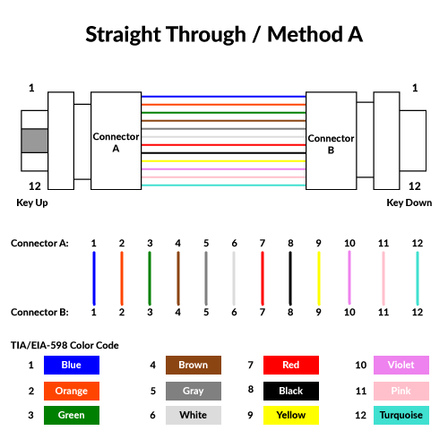
Method A – Straight Through
A “Type A” cable is also known as a straight-through cable. This cable configuration has a key-up MPO connector on one end and a key-down MPO connector on the opposite end.
This connector configuration makes the fibers at each end of the cable have the same fiber position. The fiber located at position 1 of connector “A” on one side will arrive at position 1 at connector “B.”
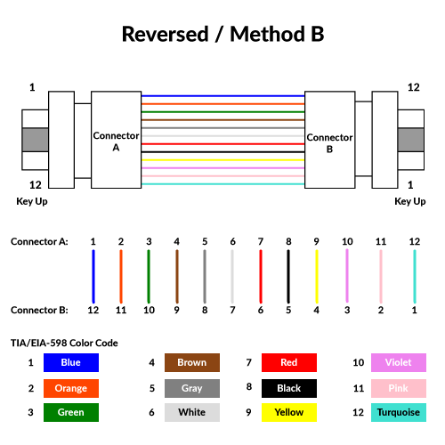
Method B – Reversed
A “Type B” cable is also known as a reversed or “flipped” cable. This cable configuration has a key-up MPO connector at each end.
This connector configuration makes the fibers at each end of the cable have an inverted position. The fiber located at position 1 of connector “A” will arrive at position 12 on connector “B.”
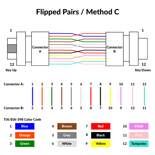
Method C – Flipped Pairs
A “Type C” cable is also known as a pair “flipped” cable. This cable configuration has a key-up MPO connector on one end and a key-down MPO connector on the opposite end.
This configuration has each adjacent pair of fibers at one connector flipped at the other. This means each “pair” is crossed. For example, the fiber at position 1 on side A connects to position 2 at the other end of the cable. The fiber at position 2 on side B connects to position 1 on the connector on side A.
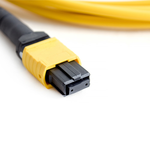
A Female MTP® Connector
The image below shows a typical Female MTP® connector, the two larger holes at the end of the connector are locator sockets. In between those are the twelve fibers, two rows of six.
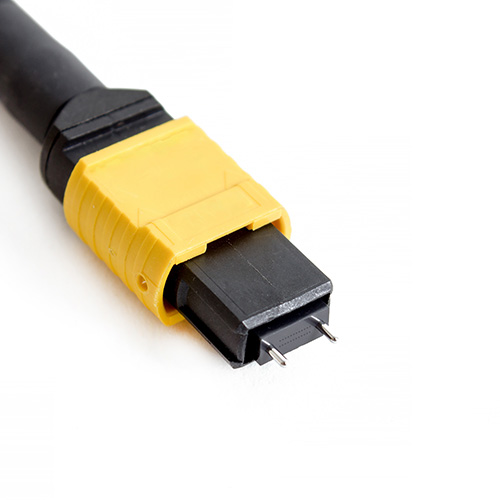
A Male MTP® Connector
The image below shows a typical Male MTP® connector, the two silver prongs are used to locate into the locator holes at the end of a female connector are locator sockets. In between those are the twelve fibers, two rows of six.