This article is also posted on our e-commerce store patchcordsonline.com.

Crosstalk is a complicated subject to grasp, especially where the “Near” and “Far” ends are. In reality, both ends of the cable are both! They only reference points to demonstrate where the signal originates for the test…
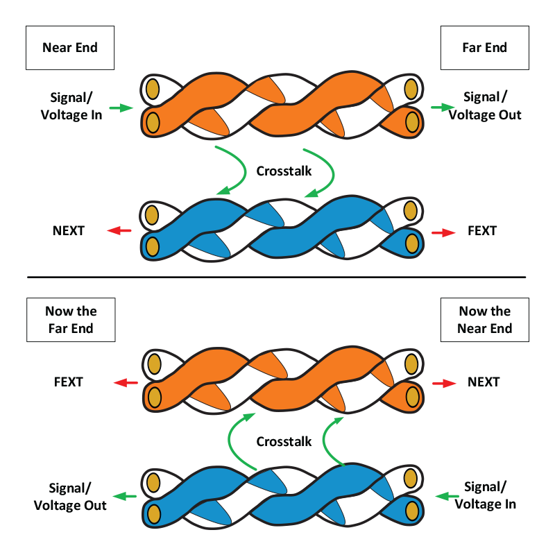
The first diagram in this article shows exactly what happens and how the “concept” of what is the Near and Far ends depending on which end the signal originates from. The diagram shows a cable tested from either end, where the two ends are, and where the NEXT and FEXT signals are in relation to the originating signal.
When a signal legitimately travels down a pair of wires in a cable, the signal emerges from the other end as it is supposed to, but the field that the signal creates around that pair “bleeds” over to the other pair in the test. The crosstalk creates a specific voltage in that wire that will emerge out of both ends, the near end, and the far end. The following sections describe the different types of crosstalk and what the measurements mean.
Near-End Crosstalk (NEXT)
The technical definition is “Interference between two pairs in a cable. This is measured at the same end of the cable as the “interfering transmitter.” What this means is that one pair can interfere with another pair at the end that is doing the transmitting at the time. In reality, the transmitting cable will interfere down the cable to the other end, but the interference will be the greatest at the end where the interfering signal is transmitted from, called the “Near” end.
For example, a cable can be plugged into a network switch, and that switch is sending data (sending an electrical signal); that electrical signal will travel down the transmit pair interfering with the other pairs in the cable at the connector. That is where the NEXT measurement is taken. It is one of the most important measurements when testing a cable (except for Power Sum NEXT); it is a reasonably conclusive test for the actual manufacturing quality of the cable itself or whether the cable itself is damaged. One of the causes of NEXT is the way that the pairs are inserted into the connector itself. If the individual pairs are not twisted right up to where they enter the connector, then there is a potential for crosstalk issues, commonly found with homemade cables. It’s hard to make cables correctly, and the temptation is to untwist the pairs more than they should be to make the connector fit easily, but this will introduce a potentially unacceptable amount of NEXT interference.
So how does one twisted pair interfere with another? When a current flows through any wire, it creates an electromagnetic field. This electromagnetic field from the transmit pair can “bleed” over to receive pair. This causes a multitude of issues, such as slow data speeds, etc. if you have a managed network switch, you can look at the interface statistic. NEXT will manifest itself by causing Runts, CRCs, and framing errors. This electromagnetic field becomes stronger as the frequency of the signal increases until, eventually, the electromagnetic field is so strong it will make the connection fail. You will see a frequency figure on the jacket of network cables. This is the frequency that the manufacturer has tested the cable up to before it reaches failure.
Power Sum Near-End Crosstalk (PS-NEXT)
This is the same as NEXT but is a calculation of the sum of unwanted signals from all the other pairs (in every combination) in the cable that affect the “victim” pair. Standards such as 10BASE-T and 100BASE-T only use two pairs in a cable, but the 1000BASE-t standard uses all four pairs in a network cable, which is where the Power Sum figure may be more relevant.
A cable that passes the PS-NEXT test should deliver superior performance for Gigabit and ten Gigabit networking deployments or any other network protocol that uses simultaneous parallel transmission. Using the PS-NEXT test cables can be “graded” rather than just being given a Pass or a Fail score. Cable grading is measured, in decibels, at a variety of frequencies that fall within the operating bandwidth of that cable. There are 7-grade levels, each one of which is 3db wide. The higher the grade, the better the performance of the cable. The 3db measurement is in the NEXT/PS-NEXT margin at 100Mhz and has a signal power difference of 2X.
Far-End Crosstalk (FEXT)
As the name suggests, it’s the same measurement as above (measuring the effect on one pair to another) but at the other end of the cable from the transmitting device. The effect is less than the near-end measurement as it is measured at the far end of the cable.
Power Sum Equal-Level Far End Crosstalk (PS-ELFEXT)
This measures the sum of the unwanted signals from pairs on the far end onto a pair on the near end.
Interference from cables around the cable in question. You can look at it as one pair as the “intruder” or the “aggressor” and the affected pair as the “victim.” Unlike the other cross talk types mentioned earlier, it is only caused by the balanced “signal-coupling” or the signal from one cable intruding on the other. Alien cross talk is not too much of an issue when using Cat5e and Cat6 for 100 Mbps or gigabit applications but is the most impactful issue for 10-gigabit applications. Even though Cat6 is capable of 10 Gigabit speed (under certain situations described in the Category Comparison article), Cat6a cable has a spline that separates the pairs at a consistent distance (just like early Cat6) to keep Alien Cross Talk to a minimum. Shielded Cat6a will eliminate Alien Cross Talk.
So what are the actual effects of Alien Cross Talk? The main symptoms are re-transmissions, which will cause significant slowdowns. These slowdowns will be random, causing unpredictable results. In extreme cases, the network equipment will negotiate a slower speed.
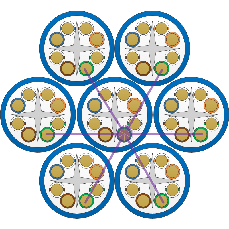
The image to the right shows how the integral spline keeps the pairs evenly separated without having to cut open one of your cables! It also shows how Alien Cross Talk acts between the individual cables in a bundle of cables.
Alien Crosstalk (AXT)
Interference from cables around the cable in question. You can look at it as one pair as the “intruder” or the “aggressor” and the affected pair as the “victim.” Unlike the other cross talk types mentioned earlier, it is only caused by the balanced “signal-coupling” or the signal from one cable intruding on the other. Alien cross talk is not too much of an issue when using Cat5e and Cat6 for 100 Mbps or gigabit applications but is the most impactful issue for 10-gigabit applications.
Even though Cat6 is capable of 10 Gigabit speed (under certain situations described in the Category Comparison article), Cat6a cable has a spline that separates the pairs at a consistent distance (just like early Cat6) to keep Alien Cross Talk to a minimum. Shielded Cat6a will eliminate Alien Cross Talk.
So what are the actual effects of Alien Cross Talk? The main symptoms are re-transmissions, which will cause significant slowdowns. These slowdowns will be random, causing unpredictable results. In extreme cases, the network equipment will negotiate a slower speed.
The image to the right shows how the integral spline keeps the pairs evenly separated without having to cut open one of your cables! It also shows how Alien Cross Talk acts between the individual cables in a bundle of cables.

Bad Ethernet Cables

Yes, lousy Ethernet cables can cause all sorts of random and annoying issues. So why are we mentioning them in an article about crosstalk?
There are several situations where cables can cause excessive crosstalk and, therefore, reduce performance (either consistently or randomly) or do not work at all.
We have talked about the different types of crosstalk and what they mean, but why does it happen in the first place?
For brand new cables, the quality of the wire and the manufacturing process is essential. The lower quality cable on the market will not have the twists on the individual pairs accurately spaced or twisted, and the overall twist will also suffer the same issue. This issue leads to crosstalk and underperformance. That cable is then used to manufacture a patch cord, and that process is also inferior; plug connection and molding process specifically, then you have a “bad” patch cable. It’s essential to buy high-quality patch cables if you want a reliable network!
Good cables go bad, like everything in life, you have to look after them if you want them to last. If you coil a cable too tightly, bend it too sharply, or pull it too hard, you are altering its characteristics. Your cable is now going to suffer the effects of some or all of the crosstalk effects described above.
Mistakes when making patch cables this is one of the most common issues of performance issues and crosstalk mayhem. All network equipment expects the cables that are connected to it to follow either the T568A or T568B standard. If you don’t, then you will create split pairs, and that will cause excessive crosstalk.
Symptoms of a Bad Network Cable
Bad cables don’t just fail to the point of not working. They will produce different symptoms depending on their state AND the type of load they have.
Generally, you will see:
- Connected interfaces dropping and connecting randomly
- Complete (and sometimes sudden) loss of connectivity
- Some traffic is ok, and others are not
A real-world example is a user on a wired workstation with a damaged patch cable. When they are browsing the web, which (usually) involves light connectionless traffic, everything performs as it should. However, when they try and copy a large file to a network location, that transfer is slow and may even fail.
The crosstalk effect from that damaged cable will cause error conditions that make the connected network equipment have to re-transmit or create error conditions that make that interface go into an error-disabled state and shut down.

